
Automotive security is really exciting and is an interesting topic of study for many security researchers. Automotive and hardware, for the most part, has always been off the radar. These hacks are always more difficult to pull off and at the same time, they are potentially more devastating. With the arrival of Self Driving cars like Tesla, Automotive security will only become more important.
When you are driving a car today, you are driving a hugely powerful computer that happens to have wheels and steering.
Today, when you drive a car, there’s nothing that is not mediated by a computer. And at the core of all this is the Controller Area Network or simply called CAN or sometimes CAN Bus, a central nervous system of a car responsible for intravehicular communication. This tutorial is going to be a guide for car hacking as safely as possible on reverse engineering CAN packets.
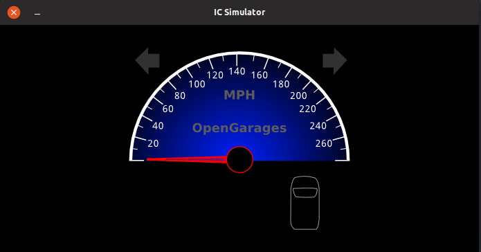
To practice CAN-Bus exploitation we will be using an ICSim package from Craig Smith. ICSim includes a dashboard with speedometer, door lock indicators, turn signal indicators and a control panel. The control panel allows the user to interact with the simulated automobile network, applying acceleration, brakes, controlling the door locks and turn signals.
“Car Hacking 101: Practical Guide to Exploiting CAN-Bus using Instrument Cluster Simulator” is a series of articles, where
Part 1 is all about Setting up the Virtual Lab
Part 2 is about Exploiting the CAN Bus
Part 3 is about SavvyCAN and doing this on a real car [TODO]
Part 1: Setting Up the Virtual Lab
The goal of this tutorial
The primary goal of this tutorial is to help you get started with Automotive security. Entry barrier to Car Hacking is much higher compared to any other security fields. I hope this tutorial can play an important role in helping you clear the entry barrier.
While Car Hacking and Automotive Security is a much broader field, this tutorial only focuses on Controller Area Network(CAN) and limited to Sniffing CAN traffic, analyzing them, reverse engineer and perform replay attacks on automotive.
While it is true that we will be performing this attack/tutorial on an Instrument Cluster Simulator, this can very well be transitioned to a real car with additional hardware. I will talk about the extra hardware needed towards the end of this article.
The goal of this article is to help you get started in automotive security and/or car hacking easily without spending a lot of money on hardware.
This is NOT a “Zero to Hero in Car hacking to make you expert in X minutes” article, instead, this article just aims to help you just get started with car hacking in a simulator.
This article will help you learn
- functioning of CAN
- Gaining access to CAN via OBD-II
- Sniffing the CAN Traffic
- Analyzing and reverse-engineering the CAN Traffic
- Replay Attack
- Denial of Service in CAN Network [Part 3 TODO]
- Playing with your CAN packets using Python [Part 3 TODO]😉
Prerequisite
If you decide to practice this tutorial, you would need:
- Any Linux distributions (I will be using Ubuntu)
- can-utils
- ICSim (ICSim is an opensource Instrumentation Cluster Simulator)
Can be downloaded from https://github.com/zombieCraig/ICSim
Introduction to CAN
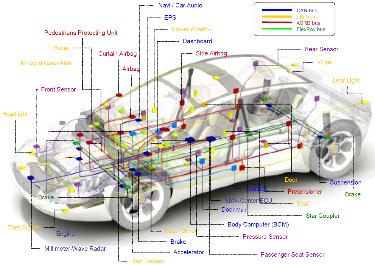
Controller Area Network aka CAN is the central nervous system that enables communication between all/some parts of the car. Before CAN was originally developed by BOSCH in 1985 as an intra-vehicular communication system, automotive manufacturers used point-to-point wiring systems. As we started having more and more electronic components in the cars, this only became bulky and too expensive to maintain. This problem was then fixed by replacing it with CAN.
In simple terms, CAN allows various Electronic units in cars to communicate and share data with each other. The main motive of proposing CAN was that it allowed multiple ECU to be communicated with only a single wire. A modern car can have as much as 70 ECUs. In a car, you can have components like Engine Control Unit, Airbags, Transmission, Gear Unit, Anti-lock braking system or simply ABS, infotainment systems, climate control, Windows, doors, etc. In order for all these units to communicate with each other, point-to-point wiring would have been so bulky. Imagine, every component connected to every other component, this would have been a real mess to diagnose for any troubleshooting. But with CAN, this can be replaced with single wire and communication between each unit is much simpler.
The CAN-Bus could be thought of as a noisy, crowded, slower version of Ethernet LAN except that the traffic is UDP rather than TCP.
It is worth noting that not all automobile control systems use CAN and also CAN is not only the communication protocol used in an automobile system. There could be other protocols such as Bluetooth, GSM/LTE cellular networks, satellite radios, LIN, etc. You should know that CAN is not the only attack surface, there could be many.
Working of CAN
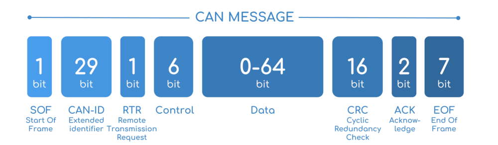
A car can have multiple nodes that are able to send and/or receive messages. This message consists of essentially an ID, which is a priority of the message and also it can contain CAN message that can be of eight bytes or less at a time.
If two or more node begins sending messages at the same time, the messages sent with the dominant ID will overwrite with that of less dominant. This is called priority-based bus arbitration. Messages with numerically smaller value IDs are a higher priority and are always transmitted first. This is how a node detects that higher priority messages are being placed on a bus.
Message from Brakes has a higher priority than a message from the audio player.
Note down that, Lowest ID = Highest Priority.
If two or more node begins sending messages at the same time, the messages sent with the dominant ID will overwrite with that of less dominant.
CAN bus consists of two different wires. As it is a bus, multiple devices can be connected to these wires. A CAN frame has 3 major parts:
- Arbitration Identifier
- Data Length Code
- Data field
Let’s have a look at the CAN data frame:
What if CAN was never invented?
This is a legit question that must be going through your head, as there are many other buses that can be easily implemented but why CAN? Before the CAN bus was invented, automotive manufactures used to do point to point wiring systems, if you have three components in the car, all three components were connected to each other with a point to point wiring system.
Consider these three components are steering system, gear unit, and ABS. Now on a typical point to point wiring system, you need a steering system to be directly connected to a gear unit and to the ABS as well with wires. Also, your gear unit needs to be connected to the ABS and Steering System, with a bunch of wires. This is perfectly fine with cars with fewer components. Can you imagine this in a modern car that has as much as 100 different ECU and other components? This is going to be messy and bulky! Also impossible to identify faults in the wiring system, (if any), the diagnosis would have been a real nightmare, and very much expensive to maintain.
This is when automotive manufacturers came up with the idea of CAN.
The point to point wiring problem can be replaced with two wires, i.e, CANH and CANL, CAN HIGH and CAN LOW respectively. Now, this way communication is much faster, simpler and very easy to diagnose.
Why Should you care about CAN?
It is because CAN is being used in pretty much every car, this is mandated by law so CAN is not going anywhere soon. Also, CAN bus was not developed keeping modern security in mind.
Okay, How do I access CAN Bus in a real Car?
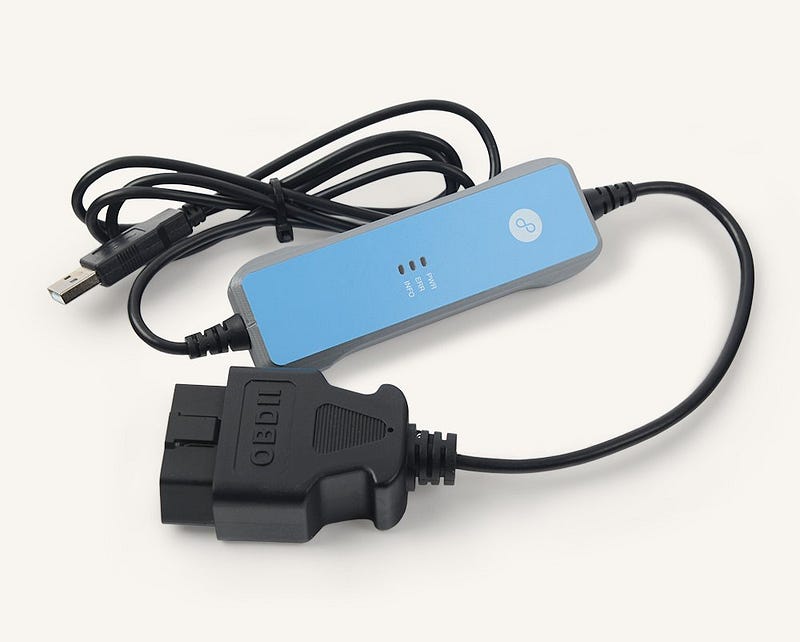
In order for you to access the CAN bus in your car, you need to have access to the onboard diagnostic port, aka OBD. While there may be hundreds of other diagnostic standards and ports, basically all the cars these days use OBD-II. This is exactly what your car mechanics usees to identify the faults in your car. OBD is the most direct access to CAN. Locating OBD-II is pretty easy. This is located somewhere near the passenger’s seat or driver’s seat. And this should be accessible without the need of a screwdriver.
This is how exactly an OBD looks like.
If you are wondering about the pinouts of the OBD, here’s the pinout for the OBD port.
If you look carefully, pin 6 and pin 14 are the same CANH and CANL that I had mentioned earlier.
Hardware and Software Needed to access CAN via OBD
In order for you to interact with the CAN bus, since now you already know you need an OBD port, you need something like USB to CAN because your computer can’t talk to CAN directly. You need something that connects to the OBD-II port via USB so that you can send/receive the CAN packets. Also on the software, you need something that can read and/or write CAN packets as well as encode and/or decode the CAN packets. With a little bit of hardware and software, you definitely can hop into the CAN.
Hardware
The hardware needed for you to connect to the OBD-II can be easily found in the market. There are expensive as well as inexpensive hardware devices. High-end devices include Kvaser and EMS, which are expensive and overkill.
You have USB2CAN, a native can interface for Linux that offers great value for money.
Also, many times you will come across this ELM327, Bluetooth based devices, they are terrible for hacking for a reason that they have slower data rates and you will end up losing so many packets.
Macchina M2
Macchina M2 is my personal favorite one. Macchina M2 is an opensource automotive interface that allows you to communicate to the CAN bus via OBD-II. The best part about Macchina M2 is that it is modular, meaning you can add WiFi, GSM, LTE, BLE modules on top of M2. M2 has 2 CAN channels. M2 also has LIN 😉 You can find more about Macchina M2 here.
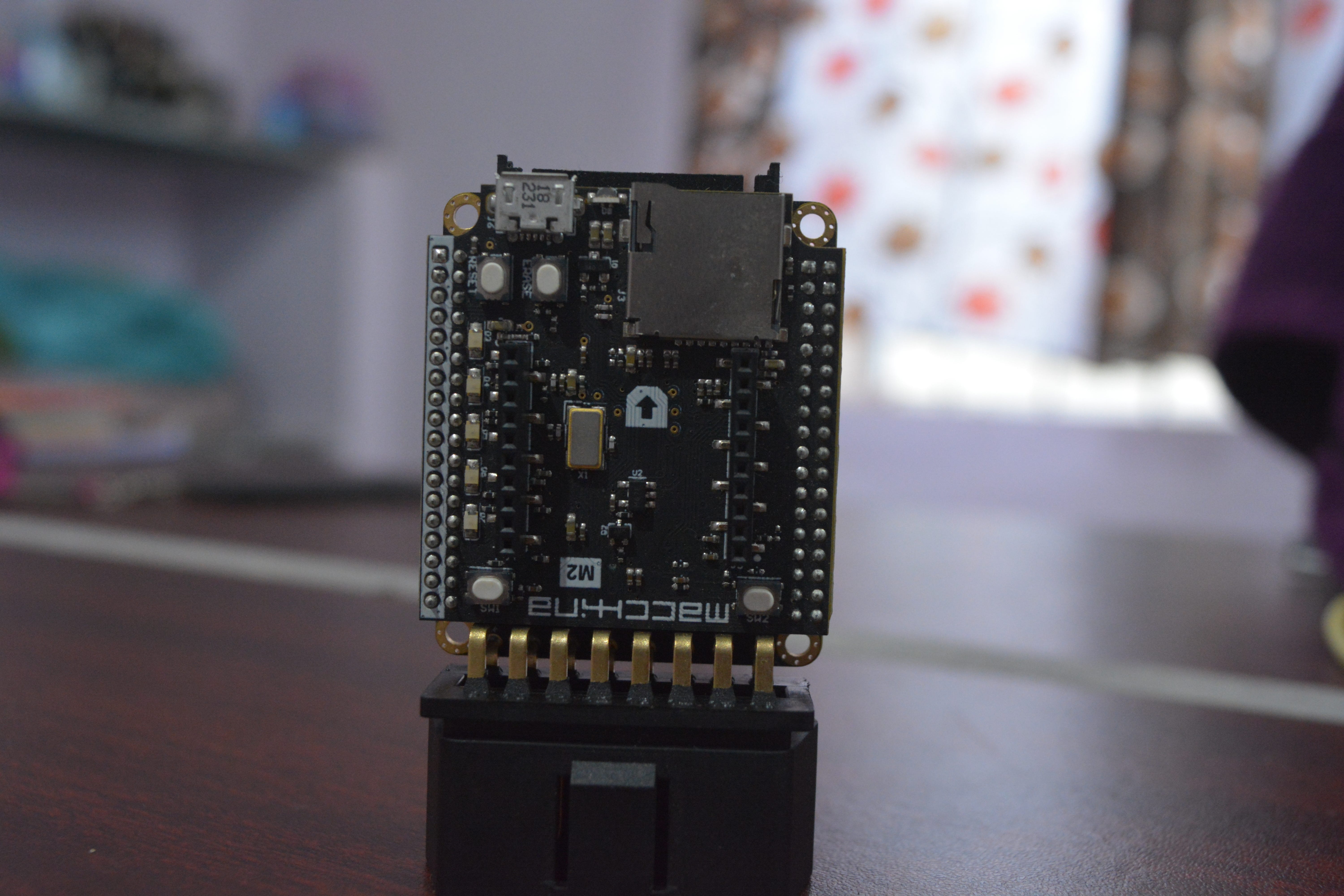
I have used USB2CAN and Macchina M2, they provide great value for money and does the job.
CLX000
Another low-cost option is the CLX000 from CSS Electronics, which lets you log and stream CAN data for e.g. car hacking purposes. Data can be visualized in the free open-source Wireshark software and a plugin enables useful reverse engineering functionality.
CLX000 is great for visualization and telematics.
You can find more information about CLX000 here, they’ve some great articles on CAN as well.
I would recommend going through their blogs: https://www.csselectronics.com/screen/page/reverse-engineering-can-bus-messages-with-wireshark/language/en
Software
On the software side, you have SocketCAN, can-utils, vcan built into the Linux kernel. They serve the purpose of sending and receiving the CAN packets, encode and/or decode them.
You also have Wireshark that can analyze CAN packets.
If you want to learn more about CAN exploitation without worrying to harm your Car, ICSim is the tool to go for!
Setting up the virtual Environment
The best and inexpensive way to practice car hacking is by running an instrumentation cluster simulator. Thanks to Craig Smith and his open-source repo called ICSim. Using ICSim, it’s pretty easy to set up and inexpensive to learn CAN-Bus exploitation.
Let’s do the setup.
Instrument Cluster Simulator requires SDL libraries
SDL is a cross-platform development library for computer graphics and audio. Since ISCim draws and animates a virtual dashboard, this is required. This can be installed via apt-get.
sudo apt-get install libsdl2-dev libsdl2-image-dev -y
Installing CAN Utils
In order for us to send, receive and analyze CAN packets, we need CAN utils. can-utils is a Linux specific set of utilities that enables Linux to communicate with the CAN network on the vehicle. The canutils consist of 5 main tools that we use very frequently:
- cansniffer for sniffing the packets
- cansend for writing a packet
- candump dump all received packets
- canplayer to replay CAN packets
- cangen to generate random CAN packets
can-utils can be installed via apt-get
sudo apt-get install can-utils -y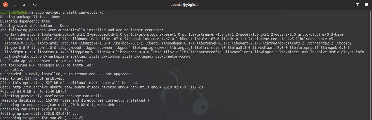
Download the Instrumentation Cluster Simulator
Instrumentation Cluster Simulator is used to generate the simulated CAN traffic.
This can be downloaded by cloning the project via a git repository.
git clone https://github.com/zombieCraig/ICSimIf everything goes well, you should see this

Preparing the Virtual CAN Network
Once you navigate inside the ICSim directory, there’s a shell script called setup_vcan.sh

The modprobe command here is used to load kernel modules like can and vcan modules. The last two lines will create a vcan0 interface in order to simulate the car network.
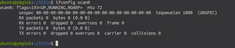
You can run the following commands to set up a virtual can interface
./setup_vcan.shTo verify vcan0 interface, ifconfig vcan0 will show
Running the Simulator
Now it’s time to run the simulator. Running the ICSim simulator at least requires two components. A dashboard and a controller to simulate the acceleration, brakes, controlling the doors, turn lights, etc. You would require at least 3 terminal windows/tabs for these to run. We would require these terminals to run dashboard, controller and another for running can-utils.
Running the dashboard
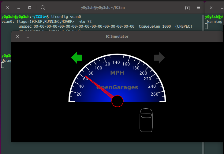
In order to run the dashboard, you could run a file called icsim with an argument vcan0, the interface we created earlier.
./icsim vcan0
At this point in time, the dashboard won’t be functioning including speedometer, turn lights, brakes or doors. It is because there is no traffic on the interface vcn0. In order to simulate traffic on interface vcan0, we need to start the controller.
Control Panel can be started by
./controls vcan0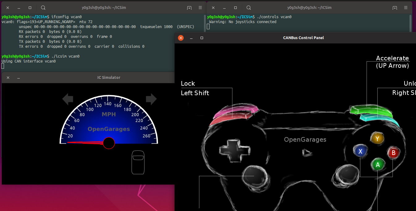
The vcan0 is the virtual CAN interface through which our ICSim will send and receive CAN frames. As soon as you start the control panel, you can observe speedometer making some fluctuations. This is because of the noise simulated by the control panel.
Once the control panel has been started, you can use keyboard keys in order to simulate traffic.
Using the key combinations below, you can make changes in the ICSim Dashboard.
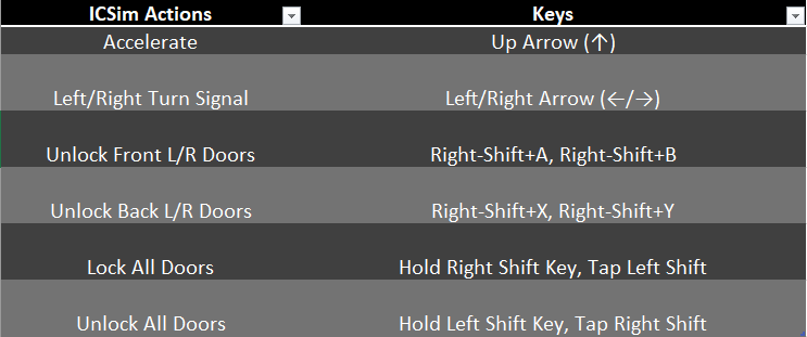
Once I press the up arrow key and left arrow key, this is what you can observe.
That’s all for the setup. If you have followed everything, you must be good to go. In Part 2, I will be talking about ways to exploit CAN traffic.
Next: Part 2: Exploiting the CAN Bus
References:
Some of the illustrations have been taken from “CSS Electronics” https://www.csselectronics.com
If you believe the illustrations listed here are yours, please feel free to message me, I will add credits to your illustrations.